ESP32 and Termux
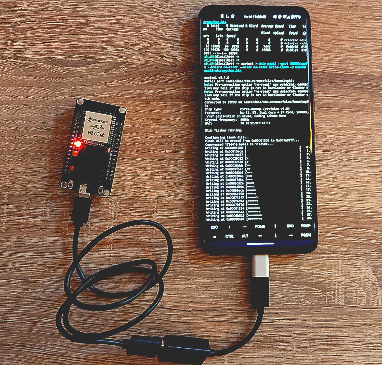
If you’re like me, you might enjoy being able to do things on your phone that you might otherwise do from your computer.
I wanted to play around with my ESP32-WROOM-32 development board, but apparently there is no online guide specifically for Termux, so I want to document the steps that worked for me as a future reference for myself and others.
⚠️ DISCLAIMER
I am not responsible for any damage that could occurr by following this guide. This is written for educational purposes.
Requirements
- any ESP32 development board will do, but in my case I will use a
ESP32-WROOM-32 - an OTG adapter
- a USB-A cable (in my case micro-USB, but it depends by your board)
- a phone with Termux installed, ideally from F-Droid
❗️ NOTE
Make sure that your USB-A cable supports data transfer. This is crucial.
Many cables I tried either did not support data transfer or were not delivering the power correctly, making the board brownout.
Getting started
The first thing you need to do is installing TCPUART transparent Bridge. This application will act as a bridge between the android Serial USB API and Termux. It will expose a local two-way TCP server that will forward the data to and from UART.
Installing a third party application is not ideal. An alternative could have been using
termux-usbthroughTermux-API, but I was facing constant disconnections and setup issues, so I settled for this app.
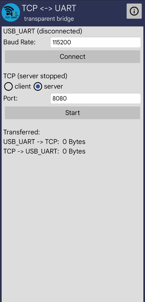
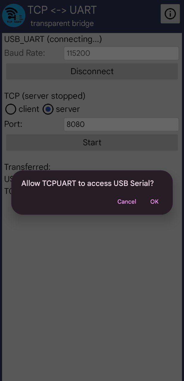
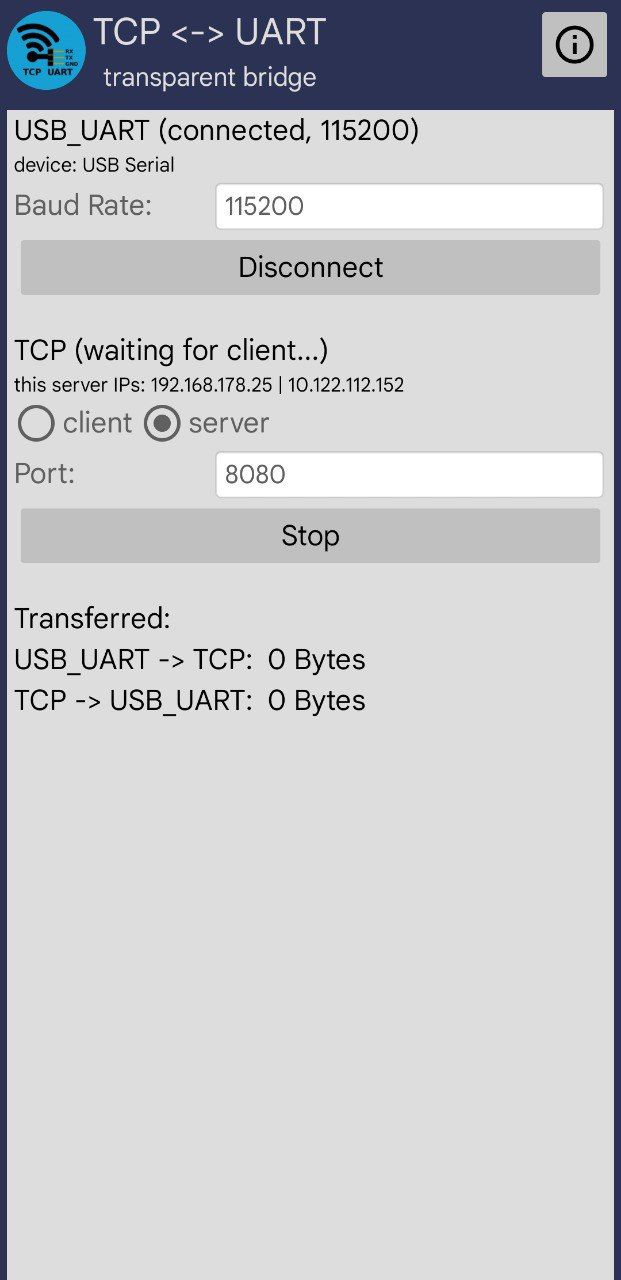
TCPUART Setup
- Set Baud Rate to
115200 - Press the
Connectbutton - A prompt should appear (see the second screenshot). Click
OK - Between
clientandserver, chooseserver - Use
8080as the port - Click the
Startbutton
Termux setup
Make sure you have the following termux packages installed. Run this command:
pkg install -y python esptool mpremote socatWe will then setup a TCP bridge virtual device file:
socat pty,link=$HOME/esp32,raw,echo=0 tcp:127.0.0.1:8080 &If it was executed successfully, the command should not print any output and socat will run in background. A file named esp32 will be created in the Termux home folder.
Resetting the ESP32
We need to reset the ESP32 memory, so we need to reboot it into download mode.
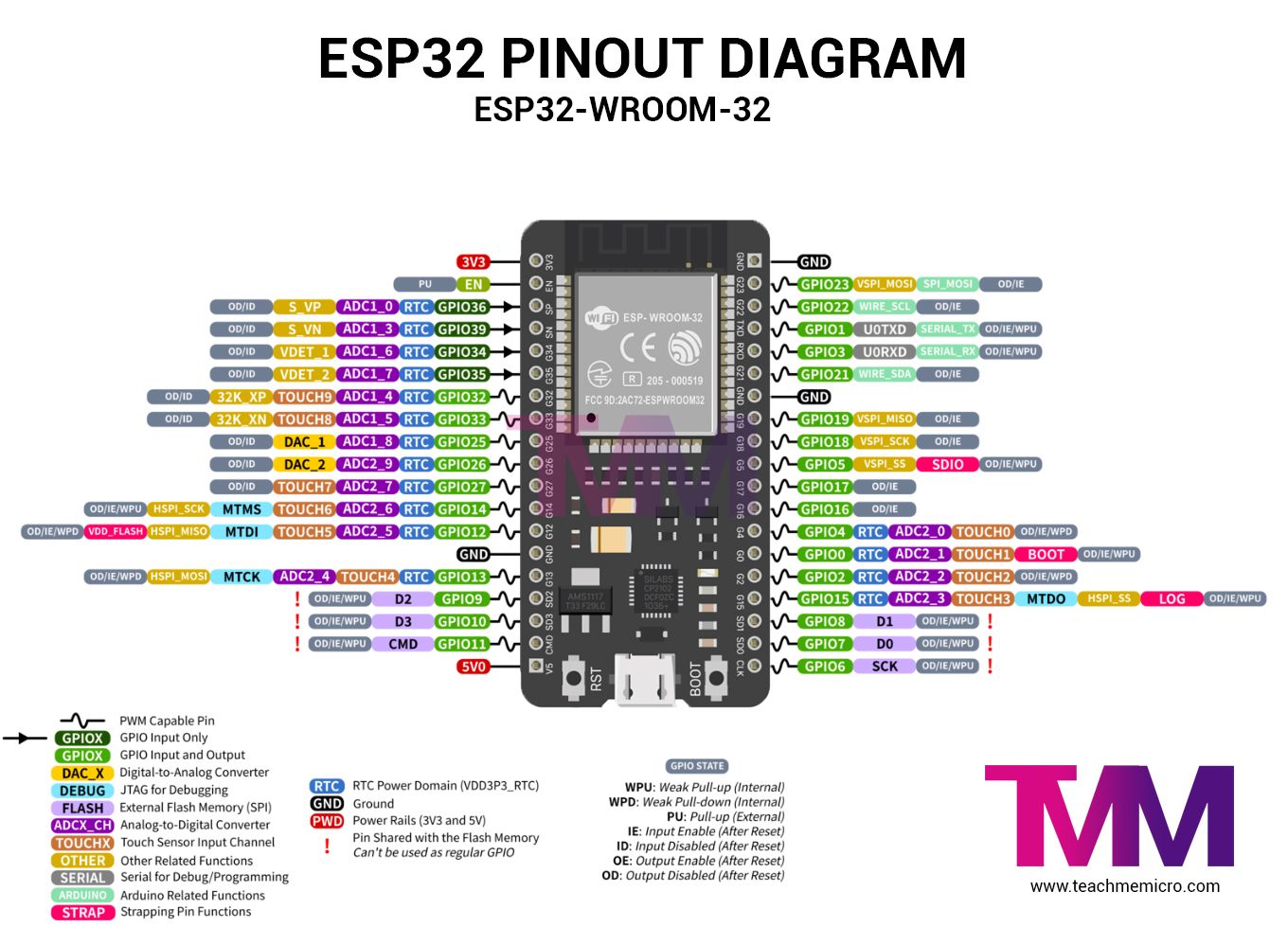
- Hold the physical
BOOTbutton on the board. The one on the bottom right in this image. - Press and release the
EN/ENABLE/RST/RESETbutton (basically the other button) - Release the
BOOTbutton - The device is now in download mode
To reset the ESP32, run this command on Termux:
esptool --chip esp32 --port $HOME/esp32 --before no-reset --after no-reset erase-flash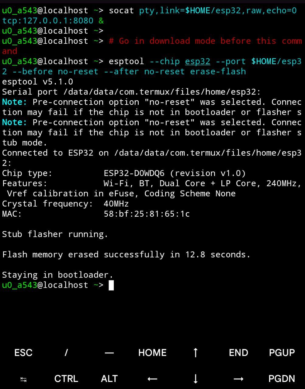
Flashing the Micropython firmware
We now need to flash Micropython on the ESP32.
The firmware link is obtained from https://micropython.org/download/ESP32_GENERIC/.
Run these commands on Termux to download and flash the firmware. Remember to go into Download mode before running the second command:
curl -L https://micropython.org/resources/firmware/ESP32_GENERIC-20250911-v1.26.1.bin -o esp32-micropython.bin

esptool --chip esp32 --port $HOME/esp32 --before no-reset --after no-reset write-flash -z 0x1000 esp32-micropython.bin
❗️ IMPORTANT
After the flash is complete, press and release the
ENABLE/RESETbutton in the board to exit download mode.
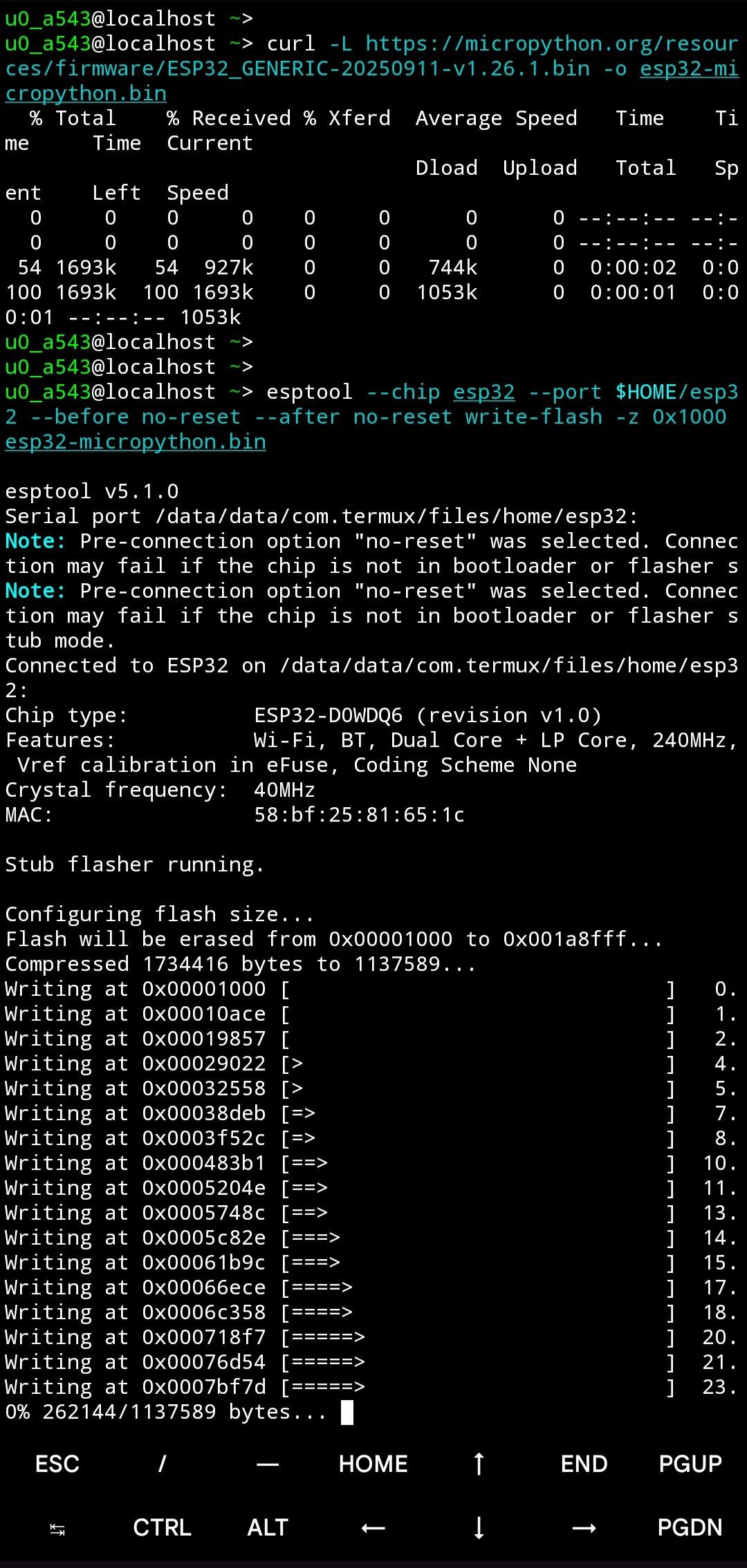
🎉 Success
Congratulations, Micropython should now be flashed in your board.
Next steps
If you want to try the Micropython REPL, run this command:
mpremote connect port:$HOME/esp32 replBy the way, there is also minicom if you want to interact with the REPL:
minicom -D $HOME/esp32 -b 115200 # Quit using Ctrl-A QIf you want to upload a program that will run on the ESP32 boot, without the need for it to be connected to your phone:
- Create a file named
program.pywithnano(or any other editor) and put it in your$HOMEdirectory - Inside it, write the code you want. The code I will be using is:
import machine
import time

# Built-in LED on most ESP32 boards (GPIO 2)
led = machine.Pin(2, machine.Pin.OUT)

print("Starting LED blink...")
print("Press Ctrl+C to stop")

try:
    while True:
        led.on()
        print("LED ON")
        time.sleep(1)
        led.off()
        print("LED OFF")
        time.sleep(1)
except KeyboardInterrupt:
    led.off()
    print("Stopped")
It will blink the builtin LED on the board every second, and will output the logs in the UART serial connection.
- Uploading the code:
mpremote connect port:$HOME/esp32 cp $HOME/program.py :main.py- To run it immediately:
mpremote connect port:$HOME/esp32 run $HOME/program.py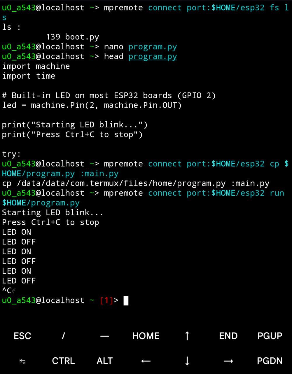
Useful mpremote commands
List files
mpremote connect port:$HOME/esp32 fs lsView a file
mpremote connect port:$HOME/esp32 fs cat main.pyDelete a file
mpremote connect port:$HOME/esp32 fs rm unwanted.pyInteractive REPL
mpremote connect port:$HOME/esp32 replConclusion
Termux is linked against Bionic Libc, and in my phone specifically it runs on aarch64, so many prebuilt binaries will not work. This means that I could not compile firmware binaries from scratch, as I could not setup a toolchain for it.
What I tried that either did not work or I gave up on trying:
- Running
PlatformIO: thextensa-esp32-elf-g++binary would not execute, as it is compiled for another architecture - An Ubuntu proot with
PlatformIO - Using
esp-idf - Rust’s
espflash,espup,esp-rs - To connect to the
UARTserial:termux-usbandTermux: API. It would disconnect often and get a new device identifier each time, requiring to accept the permission each time. It was not a very practical solution, and I did not even get to making theUARTcommunicate.
I believe that there exists a better solution than using a third party app to use the UART serial connection. However, I was not able to make it work.